Saturday, 21 March 2020

MK-1 Preamp (3C-MOD)

This optimization is called 3C-MOD as involving the replacement of three capacitors, affecting directly all the three branches of the equalizer section of the MK-1 Preamp.

The idea behind this enhancement is to tune a bit better the 1C-MOD:
  • De-power a bit more the left side of the Treble curve 
  • Slight readjust  the precision of bass curve 
  • Recentering of the Mid curve moved from 350 ahead to 400Hz
In this picture You can see the three capacitors that need to be replaced:


WARNING :
SMD USED ARE 0805  size, VERY SMALL .. then GOOD SOLDERING SKILLS ARE REQUIRED  for perform the job!!!    With some attention ALSO A 1206 smd can be used.

If We compare the effect of the 3C-MOD with the 1C-MOD We can see the following differencies:


The MID is centered more correctly at 400Hz that is the cross point between Bass & Treble controls.
 As the Q of MID filter  is slightly increased , there wil be less interference with the Bass control range.


As usual let's give a look at my preferite setting  by turning clockwise by 1\4 turn both Bass & Treble knobs:

Even more personality rising if the result compared with  the  already good 1C-MOD and let's forget about the original flatten PIZZA of the original MK-1!!.  

:-)

 Now ....rolling down a bit the Mid knob is giving quite promising scooped tonal features:


This  is the mod actually implemented in my Cort A4..... !!!!!!!!!!


To sum Up...We can see the overall new performances here:


And  a quick comparison with the original MK-1 preamp  response:


If You like my work please consider
a little contribution using my paypal account:

Donate!
*******************************************
https://www.paypal.me/kkprince999

*******************************************
THANKS !!
KKPRINCE
:-)

Friday, 20 March 2020

MK-1 Preamp (SSP-MOD)

Even performing all the optimizations done in the 1C-MOD & 3C-MOD.... We still have a problem to address...
The Treble control range is still affected in a significant way by the level of bass control applied.

This is unbearable HIGH with standard MK-1.... but  partially addressed in my 1C-MOD and 3C-MOD.
We can see a -6dB loss in the 3C-MOD.  In the standard MK-1 We would have  more than  8 Db loss !!!

the Red line is representing the equalization applied when both Bass& Treble controls are at their max level.


The SSD-MOD  arrange the Baxandall Treble & Loss filter in a way  to minimize the Treble loss INCREASING at a maximized  level  the independency between  Bass & Treble controls.

For example.....sometime is nice to get a "scooped"  sound from the bass and this is done  by:
  • CRANK UP THE BASS CONTROL NEAR TO THE MAX
  • CRANK DOWN THE MID
  • CRANK UP THE TREBLE NEAR TO THE MAX
But this requires an high level of separation between the Controls..and remember .....in  the MK-1 Bass & Treble are implemented in the same active Operational Amplifier cell.

The SSD mod does the job in a optimized manner reducing at  less than 3 Db the average Treble loss when  BASS&TREBLE controls ARE CRANKED AT 100%:


Of course even in non cranked positions the B&T controls separation works well..

In the following picture We can see  the 6 components that need to be replaced for the SSP-MOD:


Another view of  the modification on the schematic chart:


TO SUM UP:
  1. Replace both R4 & R5  (360 Ohm)  with 2  3.3k matched  resistors
  2. Replace R8 (5.1k) with one of the two  360 Ohm resistors  removed in step 1  
  3. Replace R3 (5.1k) with a 8.2k resistor.
  4. Replace C2 (22n) with a 8.2n capacitor
  5. Replace C5 with a with a 8.2n capacitor
ALL  SMD COMPONENTS TO BE USED ARE 0805 SIZE


AND FINALLY ...here the final summary equalization charts:


If You like my work please consider
a little contribution using my paypal account:

Donate!
*******************************************
https://www.paypal.me/kkprince999

*******************************************
THANKS !!
KKPRINCE
:-)


Thursday, 19 March 2020

MK-1 SSP-MOD Fine Tuning

This FINAL MOD is the one that will run on my bass for ever... cover plate screws are finally in place definitively.   Basically al the enhancements of the SSP-MOD are in place BUT the BASS curve has been reduced and slighty moved away from the MID  control area.

To acheive that the two 7500 ohm resistors for limiting the excursion of the BASS potentiometer have been replaced with two 12k resistors .

Moreover the 47n capacitor defining the BASS low pass filter has been replaced by a 56n capacitor, more appropriate in my opinion.

HERE the BASS control difference  (less invasive) in comparison with SSP-MOD:


And here (in light blue )the 3 components to replace in addition to the ones replaced with SSP-MOD:


On the circuit board in light blue the 3 components to replace in addition to the SSP-MOD


If You like my work please consider
a little contribution using my paypal account:

Donate!
*******************************************
https://www.paypal.me/kkprince999

*******************************************
THANKS !!
KKPRINCE
:-)


Wednesday, 18 March 2020

Cort A4 -----> Adjust the height of the Hipshot bridge

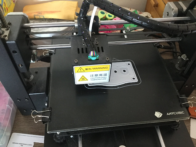
I personally think the Cort A4 Hipshot bridge is by default too low and then ... to get a proper buzzless action I need to raise the regulation screws too much ...at a point they go almost out of thread with a weird angle of the saddles.....so i printed an 1mm shim to be placed under the bridge.... PLA is a very rigid material so will work well in terms of sound transfer....unless You will play the bass at kindof 55 degree Celsius... in this case the sound will become more .......HOT

:-)

I designed the shim with sketchup.... and encoded with cura with 100 % infill... the shim is exactly 1mm in my case but We can create a version with a different height... 1mm is perfect in my case.


This is the result but We need to drill another  hole for extending the ground wire


 Here  is the ground wire to extend OVER THE  PLA BRIDGE for touching the metal of the bridge..


Now everything os OK !!!!


We can mount the bridge back in position... please note the shim is not visible at all..


MISSION ACCOMPLISHED.....
:-)


If You like my work please consider
a little contribution using my paypal account:

Donate!

*******************************************
https://www.paypal.me/kkprince999

*******************************************

THANKS !!
KKPRINCE
:-)


Tuesday, 17 March 2020

Bartolini MK-1 upgrade - > TL062 original OpAmps replaced by a set of 3 shiny OPA2196

 This modification is a significative  enhancement that will transform any MK-1 (and I would say any other preamp stuff based on TL06x  )  into a sort of  high-end low noise professional preamp unit.  

If You want to change the tonal performances of this specific preamp... please have a look at my previous posts on the argument !


A BIG WARNING:
 This modification requires good skills on managing and soldering SMD  components and of course will KILL  your pream If You do not know what You are doing....

So if You want to apply this mod  and You are not skilled enough.... ask to a friend with proper skills in a way  to perform the operation in a  safe mode !!!!!


SO LET'S START !!!!!!


I cannot totally understand the reason why in 2021 there are  still around preamp instruments and stompboxes units based on a  Operational Amplifier designed  in 1978.......
:-(
........... come on this is not a vintage tube stuff....  it's a raw opamp!  

TL06x is a 40 YEARS OLD device used now only for saving money ... and battery power...

Nowadays ...it's a kind of traditional stuff  like Santa Claus ... offering low power  consumption and a traditional FET high impedance input stage....   

but it' s limited.... also presenting  for instance a relevant NOISE to deal with...

For the benefit of the readers basically a TL06x is a depotentiated version of a TL07x  that would perform better.... but cannot be used into a battery powered device because of the related high power consumption....

To make a long story short ............

a lot of water is passed  under the bridges since 1978 and SOME very valid alternatives DO NOW EXIST on the market !!!!!!!!

My initial choice was to use a superstar chip like the LT1352 but this costs a fortune ....so i checked for something else with a highest  possible trade-off .....

I found a winner....!!!!!!!!!

And the winner is  ......STILL a Texas Instruments device ...... 

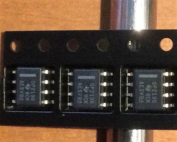
OPA2196 , 

in my case an OP2196 IDR  ,  SOIC-8 format   :-)

So I ordered 3 of them from China at  less that 2 Euro per unit .. a a price that is of course 4 time the one for a TL062 .... but .... come on ..very reasonable for  such high expected improvements...


I recommend You to read the datasheet of this Operational Amplifier  but ... to sum up:

  • OPA2196 is RAIL TO RAIL (can run from 0 to batt level) while the TL062 is not 
  • OPA2196 has 3 time less noise than TL 062 !!!!!
  • OPA2196 standby power consuption is 20% LESS than TL062 !!!!!  
  • OPA2196 slew rate is 50% BETTER than a TL062 !!!!
  • OPA2166 gain bandwidth is MORE THAN double than the one of a TL062 !!!
  • OPA2196 voltage offset is 0.1 mvolt  while TL062 has a  6mvolt offset !!!!
  • OPA2196 voltage drift is 0.1microvolt per C° against 10 microvolt per C° of a TL062....!!!!
  • An OPA2196 WILL STILL work with a batt down to 4.5 V  while a TL062 will die  at 6V...

.... should I continue ? ?  

 :-)


  NO ... LET'S get DEFINITELY  rid of the TL062 stuff..

So  the first step is to extract the preamp from your instrument, in my case my beloved CORT A4  and put in position for removing replacing the 3 TL062 used in the circuit:

Here is the preamp  unit BEFORE the operation:


I will not use an hot air gun because I do not want to generate too much mess and heat that can change the values of the capacitors around the ICs. 
I just put extra soldering tin lead  on the IC 8 pins  for easing the removal :


The three  original TL062 ICs removed.... say Goodbye..!!!!!


:-)

An after some clean up let's solder the 3 new OP2196   ..... with a LOT of CARE and PATIENCE:


Let's put the preamp  back into my Cort A4 controls cavity

:-)


And let's check the power consumption:


WHOAAAA    is this a power consumption   ????????

Kindof 1 milliamp ....   !!!!! 

More than 500 HOURS available with a 9V Battery !!!!!

:-)


Someone worried about the final result on the SOUND...   ????


NO do not be worried .... about the SOUND...

 just BE HAPPY !!!!!!

Sound is SUPER.....


If You like my work please consider
a little contribution using my paypal account:

Donate!
*******************************************
https://www.paypal.me/kkprince999

*******************************************
THANKS !!
KKPRINCE

:-)